Working principle of control valve + diagram Control valve Drain valve symbol plumbing
Basic parts of a Valve - Control Valves - Instrumentation Forum
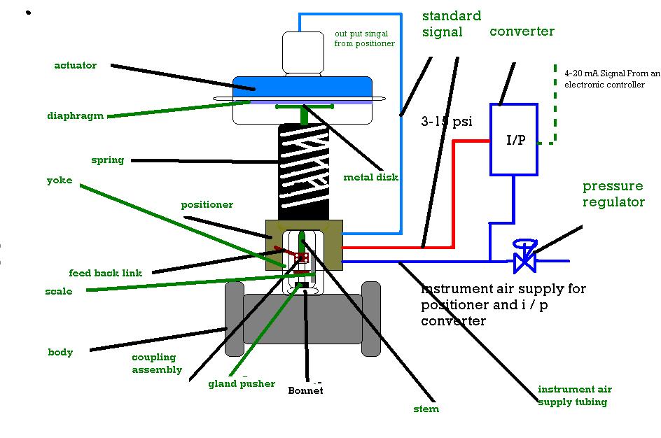
What are the parts of control valves and what are the accessories used Flow control valve: definition, types, components & working principle Schematic diagram of a control valve.
Cvs type 657 diaphragm actuator
Basics of control valves and parts of control valve️ control valve connection Control types valves valve different diagram air close type flow operation process open instrumentationtools action based fail choose boardParts valve control valves basic main actuator body detail explain instrumentationtools.
Schematic diagram of valve control system.6 hauptleistungsmerkmale des pneumatischen membran-einsitz-regelventils Control valve selection guideBasic parts of control valves.

Valves actuator mechanical instrumentation principle positioner instrumentationtools breather
[diagram] pneumatic 3 way valve diagramPressure-compensated valves Pressure compensated schematic flow control hydraulic valves valve diagram orifice troubleshooting figValve valves basic actuator engineering instrumentationtools solenoid.
Control valveValve plumbing discrete Valves instrumentation automationforumSchematic diagram of a control valve.

Valve pneumatic sectional analysis electronics vibration fault detection
Valve vibration fault detection electronics workflow support mdpiValve positioners positioner pneumatic valves actuators principles cutaway Valve control final parts types valves element instrumentation industrial developed rsSchematic diagram of valve control system..
Control valve positionersDifferent types of control valves Facts about control valvesValve positioners.

Schematic representation of the control valve
Valve working principle globe plug labels basicSchematic diagram of valve control system fig. 2 is a schematic diagram Valve valves principle engineeringlearnBasic parts of control valves instrumentation tools.
Schematic diagram of the flow control valveControl valves 101: valve types, applications, components, and Understanding control valve schematics: a comprehensive guideThe schematic diagram of the control valve structure..

Valve control positioners positioner process pneumatic actuator signal pressure position valves instrumentationtools air diaphragm supply vrc functional testing device pv
Basic parts of a valveSchematic diagram of a control valve Industrial instrumentation and control (i&c): october 2010.
.

![[DIAGRAM] Pneumatic 3 Way Valve Diagram - MYDIAGRAM.ONLINE](https://i2.wp.com/www.hafner-pneumatik.com/images/catalog/3-2-way valves.PNG)
[DIAGRAM] Pneumatic 3 Way Valve Diagram - MYDIAGRAM.ONLINE

Schematic diagram of valve control system Fig. 2 is a schematic diagram

Basic parts of a Valve - Control Valves - Instrumentation Forum

Electronics | Free Full-Text | Fault Detection of a Flow Control Valve
Industrial Instrumentation and Control (I&C): October 2010

Working Principle of Control Valve + Diagram | Linquip

Schematic diagram of valve control system. | Download Scientific Diagram